I face the same question from many buyers. They need tight parts. They need repeatable sizes. They also need simple answers. I keep it clear. Dimensional accuracy tells us how close the actual cut part is to the CAD size, in any production shift.
Dimensional accuracy in fiber laser cutting means how close the part is to the design size. In most industrial jobs, I hold ±0.05 mm with the right machine, stable motion control, tuned parameters, and clean optics. I keep accuracy stable with routine calibration and quick checks.
I do not sell guesswork. I sell predictable parts. So I frame accuracy in simple terms. I link it to beam quality, motion, thermal control, and process discipline. When I do that, customers see fewer rejects and fewer assembly issues. They also see shorter lead times.

What is the dimensional accuracy of laser cutting?
Many teams ask me if "±0.05 mm" is real. I say yes, if the stack is right. I focus on beam mode, rigid mechanics, encoder feedback, and stable cutting parameters. I also keep the table clean. Chips and dross can distort the sheet and ruin accuracy.
Dimensional accuracy for fiber laser cutting is typically ±0.05 mm on well-tuned machines. I can hold ±0.03 mm on small parts and short runs with stable temperature and good fixturing. I track drift with daily calibration, warm-up cycles, and cut tests that match real jobs.
Dive deeper
When I talk about accuracy, I break it into machine, process, and environment. I also look at how tolerance stacks up across a full sheet. Static numbers mean little if the sheet moves, heats, or bows.
What shapes real accuracy
- Machine: Beam quality (M2), linear guides, ball screws or rack-and-pinion, servo tuning, encoder resolution.
- Process: Nozzle centering, focus offset, gas pressure, pierce routine, lead-in strategy, kerf compensation1.
- Environment: Sheet flatness, workholding, thermal rise, shop temperature, vibration.
Practical tolerance bands by case
| Case | Material | Thickness | Typical accuracy | Notes |
|---|---|---|---|---|
| Prototype small parts | SS | 1.5 mm | ±0.03 mm | Short runs, tight thermal control |
| Production panels | MS | 3.0 mm | ±0.05 mm | Stable after warm-up |
| Thick plates | MS | 12 mm | ±0.10 mm | Kerf taper more visible |
| Non-flat sheets | Al | 2.0 mm | ±0.08 mm | Use pins or vacuum |
| Long parts >1000 mm | MS | 4.0 mm | ±0.10 mm | Thermal expansion accumulates |
How I hold ±0.05 mm at Kirin Laser
- I use high-brightness fiber sources with stable power. This keeps the kerf consistent.
- I use rigid frames, ground rails, and tuned servos. This keeps the path true.
- I center the nozzle and check the focus height before each shift. I use a gauge tool for speed.
- I set pierce, power, duty, and speed per thickness. I validate with a small coupon.
- I add kerf compensation in the CAM. I verify by cutting a 20 mm square and a 20 mm hole.
- I run a 10-minute warm-up path on cold mornings. This reduces drift.
- I record daily cut tests. I adjust only one parameter at a time. I avoid chasing noise.
A short story says why this matters. One aerospace client saw poor fit in rib assemblies. Holes were oval. Tabs were tight. They upgraded to a high-precision fiber laser2. I set a new cut library, added kerf comp, and locked a warm-up routine. They hit ±0.05 mm and fit issues stopped. Assembly time dropped, and so did rework.

How accurate is a laser cutting hole?
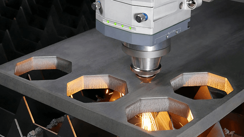
Holes challenge every machine. The path is short. Heat is high. The kerf can taper. I treat holes with care. I adjust lead-in, micro tabs, and speed to stabilize the roundness and the size.
Hole accuracy in fiber laser cutting is typically ±0.05 mm for holes over 1.5 mm. For small holes near thickness, I use micro-cycles, lower power, and a special lead-in. I often ream critical holes or use a punch-laser combo for the tightest fits.
Dive deeper
Holes bring three problems: out-of-round shape, taper from top to bottom, and heat-affected oversize. I handle these with path planning, parameter control, and design rules.
Key controls for round holes
- Lead-in: I set a short tangent lead-in3 outside the final hole. I avoid starting on the hole edge.
- Pierce: I use pre-pierce for thick plate, then I cut at steady state.
- Speed and power: I lower power and speed for small holes to reduce taper.
- Assist gas: I pick nitrogen for stainless and aluminum to avoid oxide; oxygen for mild steel if needed.
- Micro-cycles: I add a short dwell or multi-pass for holes near thickness.
- Kerf comp: I bias the hole undersize by 0.02–0.05 mm, then test and tune.
Hole size rules I use
| Material | Thickness | Minimum hole size | Expected tolerance | Notes |
|---|---|---|---|---|
| SS | 1.0 mm | 1.0 mm | ±0.05 mm | Nitrogen cut, sharp edge |
| MS | 3.0 mm | 1.5 mm | ±0.06 mm | Oxygen cut, slight oxide |
| Al | 2.0 mm | 1.0 mm | ±0.06 mm | Nitrogen cut, avoid burr |
| MS | 10 mm | 5.0 mm | ±0.10 mm | Consider drill or ream after |
I keep a simple loop for validation. I cut a test coupon with a matrix of holes from 1 mm to 10 mm. I measure each with pin gauges. I update the kerf table for each thickness and gas. I lock those into the job card. This turns hole accuracy into a repeatable process, not hope.
For tight fits, I mix processes. I cut the hole 0.1–0.2 mm undersize on the laser. Then I ream or countersink on a drill stand. This still saves time because the laser does all the complex shapes. The ream gives the fit class, like H7, with no burr.
I also watch circularity. I keep the motion loop tight with high encoder resolution. I avoid tiny segments in the CAM4. I use true arcs where I can. Smooth toolpaths give round holes. Choppy toolpaths do not.
Why is my laser cutter not accurate?
When someone calls me about poor accuracy, I check a short list first. The cause is often simple. The fix is often fast. I do not change ten things at once. I test and move step by step.
Most accuracy problems come from focus height, nozzle misalignment, dirty optics, bad sheet support, or thermal drift. I fix these with a focus gauge, a nozzle centering test, clean lenses, flat slats, stable gas, and a warm-up routine. I verify with a 20 mm square and hole test.
Dive deeper
I split accuracy issues into geometry, process, and environment. I map symptoms to likely causes. Then I confirm with a quick cut-and-measure test. This keeps me from guessing and wasting time.
Symptom to cause map
| Symptom | Likely cause | Quick check | Fix |
|---|---|---|---|
| Parts oversize | Wrong kerf comp | Cut 20 mm square | Update kerf table |
| Holes undersize | Taper / heat | Pin gauge set | Reduce power, slow speed, micro-cycle |
| Oval holes | Motion lag | Circle test path | Servo tune, use true arcs |
| One axis drift | Backlash / belt | Cut square and measure | Tighten/replace belt, check preload |
| Burr on one side | Nozzle off-center | Paper dot test | Center nozzle, change tip |
| Edge rough | Dirty lens | Visual check | Clean/replace lens |
| Warp on long cuts | Thermal rise | Infrared probe | Alternate path, pause between cuts |
| Random size shift | Gas pressure spike | Gauge log | Regulator and filter check |
My standard diagnostic routine at Kirin Laser
- Warm up the machine with a simple path for 10 minutes.
- Check shop temperature. Keep it steady within a small band.
- Clean the collimator and focus lens. Inspect for pits.
- Center the nozzle using a low-power circle test on tape.
- Zero the focus with a feeler gauge or auto-height sensor calibration.
- Verify gas type and pressure. Purge lines if water or oil is present.
- Cut the 20 mm square and 20 mm hole on the job material and thickness.
- Measure with calipers and pin gauges5. Record results.
- Update kerf comp6. Recut and confirm. Lock the parameters.
I also teach teams to watch slats and sheet support. Bent slats lift the sheet. That changes focus mid-cut. I rotate or flip slats before they get bad. I add simple pins to hold large sheets flat. For thin aluminum, I use more supports to kill flutter.
Motion matters too. If I see axis lag, I run a circle-square test and plot error. I tune servo gains or replace belts if they slip. I avoid heavy acceleration on tiny features. Smooth wins.
Above all, I keep maintenance simple and regular. Small checks every day beat big fixes every month. That is how I keep parts tight in real production.

Which material should never be cut by laser?
I get this question a lot. Safety comes first. I always check the material list before I accept a job. Some materials release toxic gas. Some damage optics. Some catch fire. I never risk my team for one order.
I never cut PVC or vinyl because they release chlorine gas and damage optics. I avoid PTFE (Teflon), ABS, and fiberglass due to toxic fumes. I avoid beryllium copper and magnesium because of health and fire risks. For fiber lasers, I cut metals, not organics or unknown plastics.
Dive deeper
I set clear rules for my team and for our partners. I also teach customers why these rules exist. The reasons are safety7, machine health, and product quality. The list is short, but the impact is large.
Materials I never cut at Kirin Laser
| Material | Why not | Risk |
|---|---|---|
| PVC / Vinyl | Releases chlorine gas, corrodes optics and mechanics | Toxic fumes, machine damage |
| PTFE (Teflon) | Releases toxic fluorinated gases | Health hazard |
| ABS | Melts and emits cyanide-bearing fumes | Toxic fumes, poor edge |
| Fiberglass (GFRP) | Glass and resin burn and abrade optics | Dust, toxic resin smoke |
| Carbon fiber with epoxy | Resin fumes and conductive dust | Health and electrical risk |
| Beryllium copper | Beryllium dust is highly toxic | Severe health hazard |
| Magnesium | High fire risk with sparks | Fire hazard |
| Unknown plastics | Unknown fillers and fumes | Unpredictable risk |
Fiber laser scope and best practice
Fiber lasers are best for metals like mild steel, stainless steel, and aluminum. They also cut copper and brass with the right back-reflection protection and stable power control. I avoid organics with fiber lasers8. Their 1 µm wavelength does not couple well to many plastics or wood. The process is not clean or safe for those.
For any new job, I ask for the material spec sheet9. I do a small cut in a safe area. I use good extraction. I measure edge quality and burr. If something smells odd or leaves sticky residue, I stop. I do not push through unknowns.
If a customer needs plastic cutting, I guide them to CO2 lasers10, which suit many plastics, with strict safety rules. If they need one step that must be laser-safe, I propose a different method such as routing, punching, or waterjet, depending on the part.
I also train the team to watch for hidden laminates. A sheet that looks like acrylic may have PVC film. I peel any film before cutting. I also label safe stock and unsafe stock. Clear labels avoid mistakes in a busy shop.
Conclusion
Dimensional accuracy in fiber laser cutting11 is a system result. I get tight parts when I align beam, motion, parameters, and environment. I treat holes with special paths and tests. I fix accuracy issues with a short, clear routine. I never cut unsafe materials. At Kirin Laser, I hold ±0.05 mm in real jobs because I control the whole stack and I keep it simple and repeatable.
-
Learn about kerf compensation techniques and their impact on achieving precise cuts in various materials. ↩
-
Explore how high-precision fiber lasers can enhance accuracy and efficiency in manufacturing processes. ↩
-
Exploring the role of lead-ins can enhance your understanding of effective machining techniques and improve hole quality. ↩
-
Understanding CAM can enhance your knowledge of how precise toolpaths contribute to achieving round holes in manufacturing processes. ↩
-
Mastering the use of calipers and pin gauges is essential for accurate measurements, ensuring your parts meet specifications. ↩
-
Understanding kerf compensation is crucial for achieving precise cuts in laser machining, ensuring your parts fit perfectly. ↩
-
Explore this link to understand essential safety measures that can protect both workers and equipment in laser cutting. ↩
-
Learn about fiber lasers and their capabilities, which can enhance your understanding of laser cutting technology. ↩
-
Discover the significance of material spec sheets in ensuring safe and effective laser cutting processes. ↩
-
Find out why CO2 lasers are preferred for cutting plastics and how they can improve your cutting projects. ↩
-
Find the best laser cutting machine and laser cutting solutions from Kirin Laser, clicking this link to get all your needs for your business. ↩


