Long jobs create heat. Heat hurts parts and machines. You lose cut quality. You risk shutdowns. You fear missed deadlines. I have seen this many times. I share what works for me at Kirin Laser. It is clear, simple, and proven.
You cool a fiber laser cutter with a stable water chiller, clean coolant, balanced flow, and smart process settings. You keep heat away from the source, the optics, and the work zone. You set alarms, log temperatures, and maintain the loop. This keeps quality stable and protects the machine during long jobs.
I speak from the maker side. I run tests every week. I watch logs. I compare real jobs. I learned hard lessons with clients. I also learned what fixes the problem fast. I will answer the five most common questions in a direct way, and I will show a clear plan you can use today.

How to reduce burning on laser cutter?
Burn marks scare buyers. They cost rework and waste. The cause is heat, soot, and slow gas. The fix is airflow, lens care, and cleaner paths. I reduce heat at the source and keep the surface clean.
You reduce burning by using higher assist gas pressure, correct nozzle size, and tight focus height. You keep optics clean, lower dwell, and use lead-ins and micro-joints to spread heat. You optimize power, duty, and speed to match metal thickness and coating, and you cut in a sequence that lets parts cool.
What causes burning in fiber laser cutting
Burning comes from excess heat, trapped slag, and poor gas clearing. When the beam stays too long, the surface oxidizes. When gas flow is weak, molten metal sticks and burns. Dirty optics also scatter energy and create hot spots. I see burning rise when the nozzle gap is wrong or the focus sits too deep.
Practical settings I use at Kirin Laser
- Focus height: I keep it slightly below the surface for thick plate and closer to surface for thin sheet. This improves kerf clearing.
- Nozzle and gas: I match nozzle diameter to kerf and raise oxygen/nitrogen pressure enough to push slag away. For stainless and aluminum, I use nitrogen to avoid oxidation marks.
- Power and speed: I do not chase speed at the cost of heat. I use a power curve1 that maintains melt ejection with less dwell. Small parts need faster traversal or segment pauses.
- Path planning: I place lead-ins outside the cosmetic area. I add micro-joints to hold small features and reduce charring from tip-ups. I spread cuts across the sheet to avoid hot zones.
Maintenance that prevents burns
I clean the protective window and nozzle often. A small film of smoke can change the beam and cause scorch marks. I also check the coaxiality of the nozzle2 and the beam. A misaligned nozzle sends gas off-center and leaves soot.
A quick reference table I share with buyers
| Symptom | Likely Cause | Fast Check | Fix I Use |
|---|---|---|---|
| Brown edges on SS | Oxidation from air mixing | Nozzle leak or low N2 purity | Tighten fittings; use >99.9% N2; raise pressure |
| Char on small holes | Excess dwell | Piercing too long | Reduce pierce time; use single-pulse pierce |
| Soot trails | Weak gas jet | Wrong nozzle gap | Calibrate standoff; match nozzle size to kerf |
| Random burn marks | Dirty window | Window haze | Replace/clean protective window; validate beam path |
A short story that shaped my method
An auto parts client cut thin SS grills. Burn marks failed visual checks. We switched to high-purity nitrogen3, reduced pierce time by 40%, and raised traverse between small features. We also cleaned optics daily. Scrap dropped by 70% in one week.
Why is my laser overheating?
Overheating means risk. It triggers alarms. It stops the job. I treat heat as a system problem. Coolant, pump, optics, and ambient all matter. I work through each point in order.
Your fiber laser overheats because heat removal is not matching heat in. The chiller may be undersized, coolant may be dirty, or flow may be blocked. Ambient is too hot, or fans are dusty. Optics can also trap energy and heat the head. Logs and a thermometer will reveal the weak link.
The thermal chain I check step by step
I start with the chiller. I compare its rated cooling capacity4 (kW) to the laser power and duty cycle. A 6 kW source needs more than 6 kW of cooling at high duty. I then check setpoint, inlet and outlet temperatures, and delta-T. A delta-T of 3–5°C is normal for many loops. If delta is near zero, the pump may be weak or flow is bypassing. If delta is too high, the heat exchanger is saturated.
Next, I inspect coolant quality5. I sample for clarity, algae, and conductivity. Dirty coolant reduces heat transfer and corrodes fittings. I follow our Kirin Laser spec for mixture and resistivity. I replace filters at the hours we list, not when they look dirty.
I move to flow. I verify L/min against the machine spec. I check strainers, quick connectors, and bends for restrictions. I also listen for pump cavitation6. I bleed air from high points because trapped bubbles insulate hot parts.
I inspect ambient. I measure intake air temperature near the chiller and the laser cabinet. Hot rooms and blocked vents add load. I clean condenser fins and cabinet filters. I make sure the chiller has free air on all sides.
I look at optics and the cutting head. A burned protective window raises absorption and heats the head sleeve. That heat loads the cooling loop. I inspect the window under light, and I replace it if I see a tint.
Data I log and how I decide
I log inlet/outlet temps, flow, pump current, and room temp. I add a simple IR reading on the head body after a long cut. If the loop holds setpoint but the head gets hot, optics cause it. If the chiller outlet rises and stays high, the chiller is undersized or fouled.
A clear table to guide actions
| Observation | Interpretation | Action |
|---|---|---|
| Outlet temp climbs, delta-T grows | Heat exchanger overloaded | Increase capacity or lower setpoint; clean condenser |
| Flow swings up/down | Air in loop or cavitation | Bleed loop; check pump inlet; remove restrictions |
| Head hot, loop stable | Optics absorbing | Replace window; check focus lens; re-align |
| Frequent high temp alarms at night | Ambient spikes | Improve HVAC; move chiller intake; add ducting |
This simple path finds the cause fast. It protects uptime and saves the source from thermal stress.

How long does laser cooling take?
Time to cool down matters. You want short pauses. You need a plan. I give a direct answer. Then I show how to make it faster.
A typical industrial water chiller returns a fiber laser to setpoint in 3–10 minutes after a long run, if capacity matches load and ambient is stable. Cooldown depends on chiller kW, loop volume, coolant, and head mass. You can shorten time by raising flow, cleaning heat exchangers, and staging the job.
What defines cooldown time
Cooldown is a function of heat capacity and removal rate. The system stores heat in the coolant, the laser source, the cutting head, and the cabinet. The chiller removes heat using its compressor and heat exchanger. If the chiller has headroom above the steady-state load, cooldown is fast. If it barely matches the load, cooldown drags.
I measure four things: chiller capacity7 (kW), loop volume (L), coolant type8, and ambient. A larger loop stores more heat, which needs more time to remove. A glycol mix changes heat capacity and viscosity. Hot rooms lower the chiller’s efficiency.
Practical numbers I see in the field
- Small fiber sources (1–2 kW) with a 1.5–2.0 kW chiller usually cool in 3–5 minutes.
- Mid sources (3–6 kW) with a 1.2x to 1.5x capacity chiller cool in 5–8 minutes.
- High power (>8 kW) systems need 8–12 minutes unless the chiller is oversized or ambient is cool.
These numbers assume clean coils, proper flow, and no optics heating.
How I make cooldown faster
I split long nested jobs into zones. I cut a hot zone, then I jump to a cold zone. The loop has time to pull heat down while the beam moves. I also use ramp-down logic: I reduce power for fast travel cuts near the end. This reduces residual heat.
I keep condenser fins clean and I give the chiller space to breathe. I raise flow within spec to increase convective transfer. I set the chiller to a realistic setpoint, not too low. A setpoint just below the laser’s ideal temp reduces compressor cycling and time to settle.
Cooldown planning table
| Factor | Target | Effect |
|---|---|---|
| Chiller sizing | 1.2–1.5x laser thermal load | Shorter cooldown |
| Flow rate | At or above spec (L/min) | Faster heat removal |
| Ambient | <28°C intake air | Higher chiller efficiency |
| Job sequencing | Hot-cold-hot pattern | Less peak heat |
In one automotive case, the client had long sessions and shutdowns. We installed a high-efficiency chiller, cleaned the loop, and staged jobs. Cooldown went from 12 minutes to under 6 minutes, and uptime rose by about 30%.
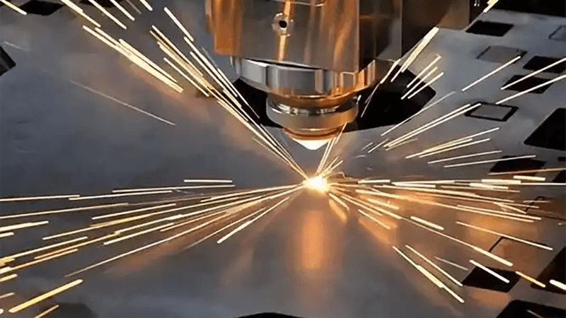
Why do lasers get hot?
Lasers get hot because energy turns to heat. Not all energy becomes a clean cut. Some stays in the source, optics, and work. I track each path and fix the bottleneck.
A fiber laser gets hot due to electrical-to-optical loss in the source, absorption in optics, and heat from the cut zone. The chiller must pull this heat away. If any link is weak—power conversion, optics cleanliness, gas flow, or ambient—heat builds up and causes drift or alarms.
Where heat comes from in a fiber laser system
- Source losses9: The diode pumps are not 100% efficient. The difference becomes heat in the source and its electronics. Efficiency improves each year, but heat is still large at high power.
- Optics absorption10: Every lens and window absorbs a small part of the beam. Dirt and micro-scratches multiply this absorption. That energy becomes heat in the head.
- Process heat11: The cut melts or vaporizes metal. Some heat returns to the material and re-radiates toward the head. Poor gas flow traps this heat at the kerf.
The full loop that must carry the heat
The chiller, pump, hoses, and channels inside the head and source must move heat out. If the pump is weak or lines are kinked, the loop cannot move enough energy. If the chiller condenser is clogged, it cannot dump heat to the room air. If the room is hot, the condenser rejects less heat.
Signs I watch and what they mean
- Rising source temperature with stable head temperature points to chiller undersize or condenser fouling.
- Rising head temperature with stable source temperature points to optics absorption.
- Temperature oscillations point to low flow or air in the loop.
How I reduce heat load at the process
I adjust focus to improve ejection so I need less power. I use correct gas pressure to keep the kerf clean. I avoid long, tight spirals on thin parts. I place pierces away from finished surfaces and reduce pierce time with burst modes when possible.
A simple cause-to-action table
| Cause | Symptom | Best Next Step |
|---|---|---|
| Source inefficiency | High coolant outlet temp | Increase chiller capacity; verify setpoint |
| Optics absorption | Head shell warms fast | Replace protective window; inspect lens |
| Poor gas clearing | Burn and spatter | Raise pressure; change nozzle; check coaxiality |
| Hot ambient | Frequent derates | Improve HVAC; clean filters; move intake |
Heat is normal. Good design channels it out. Good maintenance keeps it that way.
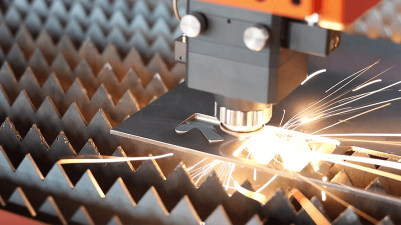
How to get laser to cut deeper?
Shallow cuts waste time. They force second passes. I aim for a clean, full-depth cut in one go. I tune power, focus, gas, and speed together.
You cut deeper by aligning focus to the melt front, increasing assist gas pressure, and matching power and speed to the thickness. Use a larger nozzle for better ejection, keep optics clean, and plan the path to reduce heat buildup. If needed, use multi-pass with cooling pauses.
Set the focus to the right place
Depth comes from moving energy to the melt front. For thick plate, I place the focus slightly below the top surface so the beam maintains power density12 through the kerf. If the focus sits too high, the top edge burns and the bottom fuses. If it sits too low, the top edge rounds and the kerf widens.
Match power, speed, and gas
I increase power until melt ejection is steady. I watch the plume and the bottom of the cut. I raise gas pressure to clear the kerf. I keep speed where the kerf stays narrow and the bottom opens. For carbon steel with oxygen, I use the exothermic help but avoid over-oxidation. For stainless and aluminum, I use nitrogen and rely on pure beam energy and gas ejection.
Nozzle and standoff
I pick a nozzle size13 that balances pressure and flow. Too small chokes the flow and heats the kerf. Too big lowers pressure and leaves slag. I keep standoff consistent with a capacitive height system. A steady gap means stable gas jet and stable depth.
Path and pierce strategy
I reduce pierce time and use stepped or single-shot pierce with validation. I avoid stacking many small features back to back in one hot area. I space them to let the plate cool. For very thick material, I allow a short pause mid-pass. I also test a two-pass cut with lower power on the second pass to clean the bottom edge.
Maintenance that protects depth
Clean optics give me consistent power at the work. A fogged window can cost several percent of power, which kills depth on thick plate. I replace worn nozzles and check coaxiality. I verify that the assist gas purity14 meets the spec, because moisture and oil reduce ejection.
Thickness-to-setup guide
| Material | Thickness | Gas | Typical Focus | Notes |
|---|---|---|---|---|
| Carbon steel | 8–12 mm | O2 | Slightly below surface | Use moderate speed; watch oxide layer |
| Stainless steel | 6–10 mm | N2 | Near surface to shallow below | High pressure; keep nozzle clean |
| Aluminum | 6–8 mm | N2 | Slightly below surface | Needs high flow; monitor reflectivity |
A client once fought shallow cuts on 10 mm stainless. We raised nitrogen to 20 bar, set focus 0.3 mm below the surface, and increased power by 8% with a small speed drop. The cut went through in one pass, and edge quality passed inspection.
Conclusion
Long jobs push fiber laser15 s hard. Heat builds fast. I keep quality and uptime by sizing the chiller right, keeping coolant clean, and holding steady flow. I clean optics, match nozzle and gas, and plan paths that spread heat. I log data and act early on small trends. These steps keep edges clean, cuts deep, and machines safe. They also protect delivery and profit.
-
Exploring the impact of power curves can enhance your knowledge of optimizing laser cutting settings. ↩
-
Learning about nozzle coaxiality can prevent issues like soot and improve cutting precision. ↩
-
Discovering the advantages of high-purity nitrogen can lead to better results and reduced oxidation. ↩
-
Understanding cooling capacity is crucial for maintaining optimal performance and preventing overheating in laser systems. ↩
-
Exploring coolant quality can reveal how it impacts heat transfer and system longevity, ensuring efficient operation. ↩
-
Learning about pump cavitation helps in identifying issues that can lead to system inefficiencies and potential damage. ↩
-
Understanding chiller capacity is crucial for optimizing cooling efficiency and performance in various applications. ↩
-
Exploring coolant types can help you choose the best option for efficient heat transfer and system performance. ↩
-
Understanding source losses can help optimize efficiency and reduce heat generation in fiber laser systems. ↩
-
Exploring optics absorption will provide insights into improving laser efficiency and reducing heat issues. ↩
-
Learning about process heat can enhance cutting efficiency and minimize heat-related problems during operations. ↩
-
Understanding power density is crucial for optimizing laser cutting processes and achieving high-quality cuts. ↩
-
Learn about the significance of nozzle size in maintaining pressure and flow for effective laser cutting. ↩
-
Explore how assist gas purity impacts cutting efficiency and quality, ensuring optimal performance in laser applications. ↩
-
Find the best laser cutting machine and laser cutting solutions from Kirin Laser, clicking this link to get all your needs for your business. ↩

